Father’s Day Thoughts – Standing on the Shoulders of Others

“You are where you are today because you stand on somebody’s shoulders. And wherever you are heading, you cannot get there by yourself. If you stand on the shoulders of others, you have a reciprocal responsibility to live your life so that others may stand on your shoulders. It’s the quid pro quo of life. We exist temporarily through what we take, but we live forever through what we give.” —Vernon Jordan

I thought a lot about my dad this Father’s Day weekend.  He passed away five years ago in June and I still miss him.  Like all fathers, he wasn’t perfect, but the lessons he taught me have had a profound impact on my life.  I wanted to share some of those lessons with you today.

Be an engineer – Plan ahead.  I can’t remember a single project that my dad took on that didn’t have a plan fully developed before he started.  Many times, he even had written diagrams and details.  He would be frustrated when we (especially my sister and I) would act without thinking ahead. It was his fundamental philosophy. He loved seeing how efficiently he could get something done.  Apply engineering discipline to problems, projects and even PLAY.  That’s right, he would have blueprints drawn up for our vacations (ok not exactly but they were fully planned).  But it all taught me the value of engineering, being thoughtful, solving problems with design, science and planning.

Work hard – My dad was never afraid to do the hard-manual work himself, mowing lawns, repairing his car, fixing something at home or working long hours to get a job out at the office.  While not unkind he had little patience for lazy people (or his own kids). He set the example with hands-on effort, blood, sweat and tears. 

Be considerate – My dad would say “leave things better than you found them”. When you can, go above and beyond when dealing with others.  If he borrowed something he expected to return it in better shape.  Being considerate was really about the golden rule. Treat others as you would want to be treated. Don’t make others have to wait on you or clean up after you.  

Details matter – Craftsmanship and precision artistry should be in all things.  My dad would say, looking at a car, a tool, or anything else, “See how the seams line up?  Notice the precision of the gap.”  You can see and feel the quality.  If you were cleaning he would help you see if you missed a spot. Underneath?  Did you get the crevices?  Check the edges.  It taught me to have an eye for detail.

Enjoy each moment – You should savor and soak in life.  Laugh and smile.  Anytime we tried something new, my dad would provide instructions: slow down, observe, enjoy and taste all the flavor. That mindfulness approach to living life transcends all the chaos, turmoil and Coronavirus pandemic world we live in.  It reminds me to look for the good and breathe it in.  Appreciate each moment and celebrate life together.

Many of us can look back to others, our parents, grandparents, friends or mentors and think how their lessons and investments in us have made profound differences in our lives.  The foundational opportunities we were given are gifts, unmerited and incredibly powerful.  Not everyone receives the same investment or shoulders to stand on.   As Vernon Jordan eloquently put it, if we stand on the shoulders of others, we have a reciprocal responsibility to live our life so that others may stand on our shoulders.  It would be unjust for me to take what I have been given and not share it with others. 

What are you doing to help others in your family, on your team or in the world?  Don’t miss the great opportunity to pay it forward, encourage others, invest your talents, time, energy and resources in helping each other.  Plan to make a difference in someone else.   “We exist temporarily through what we take, but we live forever through what we give.” 

What’s in your tea cup?

“Character is power. If you want to be powerful in the world, if you want to be strong, influential and useful, you can be so in no better way than by having a strong character.” —Booker T. Washington

I love tea.  Many of you know how much I like coffee, but you may not know how much I also enjoy tea.  I have tried many teas over the years but my current favorite is PG Tips, a popular British blend of Assam, Ceylon and Kenyan teas.  It’s interesting to me how they can all look and smell the same in the tea bag but can be so dramatically different after steeped.  You can’t know the flavor until the hot water pulls it out from the leaves.  So often in life we think we know our own character and what is core to our being, but it isn’t until the trials of life that we truly discover what is on the inside.  Like tea, our true character is revealed in the hot waters of difficulty, stress, pressure and challenges.  What we really are, what we have cultivated and nurtured on the inside spills out.  Difficulties don’t define us, but reveal the true us.   

We just crossed over the 3rd month since the start of COVID, social distancing, face masks, safer at home remote work and now economic and social justice issues. How are you doing during these difficult times?  What is spilling out of you?  What have you learned about yourself and others?  Does it make you happy or make you want to change?  These are questions I’ve been asking myself.   I must confess, I feel like I’m a bit more like Decaffeinated Lipton than PG Tips.  I am too easily frustrated and irritated at things that don’t go my way.  I don’t always listen well (my family helped me discover this).  I should be more vocal and active in supporting my fellow human brothers and sisters.  I have work to do.

As the hot waters of difficulty and change washed over my family and team, I must say, I am incredibly proud. I have seen heroic characters surface in areas I didn’t expect, compassion, generosity, optimism and leadership spill out from all areas.  I have also seen a river of creative problem-solving.

Sure, there have been moments when tempers flare and struggles with despair set in, but even in those moments we have had good conversations.  I know that we all have a list of things we have discovered about ourselves and each other.  My challenge to you today is to not let this great opportunity go to waste.  As we do with all incidents, this is a great moment to study, learn and change.  Be understanding.  Be kind but also be brave. 

What’s in your tea cup?  What would you change about yourself?  Your character spills out and becomes a powerful agent to influence the world around you. You matter.  Your character matters.  What you are inside will be revealed during difficulties.  Take this opportunity to learn about yourself and cultivate a strong character so that when it spills out it becomes a powerful and useful influence on the world. 

ATtiny85 Weather Station

Weather Station

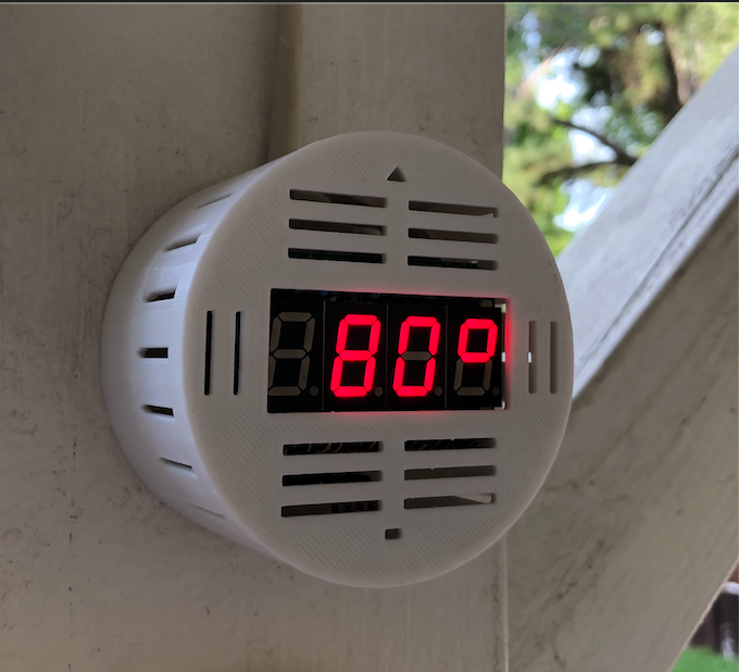
This project will show you how to build an ATtiny85 based mini Weather Station that displays temperature, humidity and pressure using four easy to read 7-segment LEDs.

Requirements

This sketch requires a version of the Wire library that is compatible with the ATtiny85 for the I2C communication to work with the BME-280 sensor. I used the ATTinyCore arduino core by Spence Konde which has a version of the Wire library that works with the ATtiny85. I was able to use the standard Adafruit_BME280 library to pull data from the BME-280. You can install ATTinyCore by putting the board manager URL in the Arduino IDE preferences:

http://drazzy.com/package_drazzy.com_index.json

Set the board to the ATtiny85 chip at 1Mhz (internal).

Circuit

Components:

  • ATiny85 Microcontroller (DigiKey)
  • BME-280 Sensor (Temperature, Pressure, Humidity) (Amazon)
  • 74HC595 8-bit Shift Register (Qty 4) (DigiKey)

Sensors

  • 7-Segment LED Display (Qty 4) (DigiKey)
  • 0.1uF Ceramic Capacitor (Qty 2)
  • 100uF Electrolytic Capacitor
  • 5V Power Supply (Alternatively you can use a 5V Solar cell, 3.7V lithium ion battery and a TP4056 constant-current/constant-voltage linear charger to charge the battery during the day).

Schematic

Circuit Board

ATtiny85 Microcontroller

Circuit Board

Programming Notes:

Code for this project is located on Github: https://github.com/jasonacox/ATtiny85-Weather-Station

I2C communication with BME-280 uses pins PB0/SDA and PB2/SCL. If you use the Tiny AVR Programmer from Sparkfun or something similar, keep in mind that it drives an LED on PB0 which will interfere with I2C communication. You will need to remove the chip from the programmer after uploading to get it to work in the circuit.

Memory Warning

This sketch uses nearly all of the ATtiny85 program storage space (8K) so you may get an overflow error if the libraries change or you add any code. To address this, I created a minimized BME280 library to reduce the PROGMEM space required. You will need to download and install the Tiny_BME280_Library library in:

~/Documents/Arduino/libraries/ directory and restart the Arduino IDE.

Display

  [ 70'] - Temperature in degree F 
  [ 24r] - Relative Humidity %
  [_970] - Pressure in hPa with rising/falling animation
  [ 21c] - Temperature in degree C 

Construction

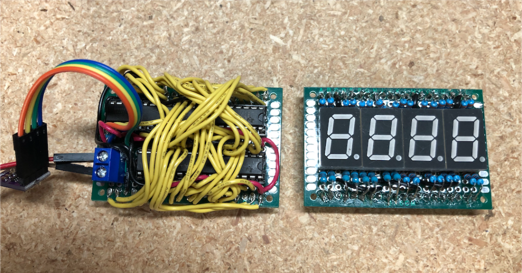
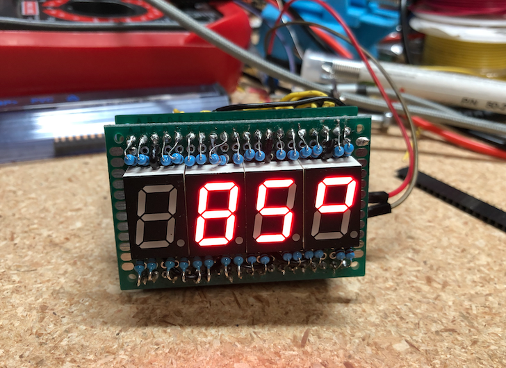
I used two circuit boards: Display and Logic board. The Display board holds the four 7-segment LEDs with the array of resistors. On the back are header pins that plug in to the logic board. The Logic board holds the 4 register chips and the ATtiny85. On the back are headers for the Display board to plug in.

Logic and Display boards: 

Both boards together and running: 

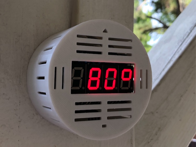
I printed a simple cylinder case (Thingiverse) to mount the weather station and have it on the back patio: 

Power Supply

The circuit will run on 5V or 3.3V. I used an existing solar panel, battery and TP4056 charger circuit to power this project with a 3.3V regulator.

Solar Power Option

  • 1 x 2.5W 5V/500mAh Solar Cell – Amazon
  • 1 x 5V Micro USB 1A TP4056 Lithium Battery Charging Board with Protection Charger Module Amazon
  • 1 x 3.7V 3000mAh 755068 Battery Rechargeable Lithium Polymer ion Battery Pack – Amazon
  • 1 x 3.3V Linear Regulator 250MA MCP1700-3302E/TO – DigiKey

ATtiny85 Ultrasonic Distance Measurement for Parking Help

After discovering the tiny but mighty ATtiny85 microcontroller, I decided to put it to use to help me park my car in the garage. Sure, I could continue to use the softball hung from the ceiling to let me know when I have the car pulled in far enough, but why not take advantage of some tech and have it show me instead? Alternatively, for these times, it is also a fun way to clearly demonstrate 6ft social distancing. 😉

ATiny85 Microcontroller

The ATtiny85 has 5 GPIO easily usable pins (technically you can even use Reset pin as a 6th GPIO but that makes it much more difficulty to reprogram). For information about how to program the ATtiny85, see my previous blog post here.

The tiny but mighty ATtiny85 Microcontroller Pinout

For my “Parking Helper” project I decided to use the low cost entry level ultrasonic distance sensor, the HC-SR04 and two 7-Segment LEDs to show the distance between the device and the front of the car.

HC-SR04 Ultrasonic Sensor

The HC-SR04 has 4 pins: VCC, Trig, Echo and Gnd. The Trig and Echo lines will be driven by the Attiny85.

HC-SR04 Ultrasonic Distance Sensor

The HC-SR04 measures distances by sending (TRIG) an sound pulse and measuring the time it takes for the ECHO. Sound travels through air at 332 meters per second at 20 °C (68 °F). Using this the unit provides a duration pulse back to the controller that can be used to determine the distance.

The speed of sound is: 343m/s = 0.0343 cm/uS = 1/29.1 cm/uS

I found a great project here where the author uses the HC-SR04 as an ultrasonic rule. Using the ATtiny85 to trigger and receive the duration pulse we can determine the distance to the parked car.

// Send TRIG HIGH for 10 microseconds 
// to trigger the HC-SR04 to send a sound pulse
  digitalWrite(trigPin, LOW);
  delayMicroseconds(2);
  digitalWrite(trigPin, HIGH);
  delayMicroseconds(10);
  digitalWrite(trigPin, LOW);

// Read the ECHO duration
  duration = pulseIn(echoPin, HIGH);

// convert the duration to cm
  distance = (duration / 2) / 29.1; 

LED Display (2 Segment)

Driving the display with two 7-segment LEDs is a bit more complicated. Each segment has 7 LEDs to form the numbers plus one LED for the decimal point. That would require 8 GPIO ports for each LED Display or a total of 16 GPIOs! The ATtiny85 has only 5 available for use so we need another way. Thankfully, we can use two low cost 8-bit shift registers (74HC585) and get by with using only 3 GPIO and still drive the 16 LEDs on the two displays.

74HC595 8-bit Shift Register to Drive 7-Segment LED Display

Here is how it works… The ATtiny85 sends the binary data for the the numbers to a first 74HC595 8-bit register using its “Data Input,” “Clock” and “Latch” lines. Once the register receives a total of 8 bits (1 byte), it will overflow the data out through its “Output” line which can be connected to the “Data Input” of another register.

We toggle the “Clock” to signal to the registers to record the value of the data line (1 or 0). We do that for each of the bits of the two bytes we need sent for each display. Finally, we have the ATtiny85 toggle the “Latch” to let the registers know when the transmission is complete. They then lock the 8 output lines (QA to QH) to high or low depending on what they recorded. These lines are connected to the individual LEDs on the 7-segment LED displays.

I found a great example of using the 74HC595 to drive multiple LED Displays here. I used that code to send the data as well as the byte arrays used to form the numbers on the LEDs. Since that project was using a common anode LED and my project uses a common cathode LED I had to flip the bits. In the code below, a one (1) value would drive the LED high (on) and a zero (0) would drive it low (off).

/* Set up 7-segment LED Binary Data

     |--A--|
     F     B
     |--G--|
     E     C
     |--D--|   H - Decimal

     0b00000000
       ABCDEFGH
  */  
  numArray[0] = 0b11111100; // 0 - Zero
  numArray[1] = 0b01100000; // 1 - One
  numArray[2] = 0b11011010; // 2 - Two
  numArray[3] = 0b11110010; // 3 - Three
  numArray[4] = 0b01100110; // 4 - Four
  numArray[5] = 0b10110110; // 5 - Five
  numArray[6] = 0b10111110; // 6 - Six
  numArray[7] = 0b11100000; // 7 - Seven
  numArray[8] = 0b11111110; // 8 - Eight
  numArray[9] = 0b11110110; // 9 - Nine
  numArray[10]= 0b00000000; // All Off

Circuit Schematic

Pulling it all together, here is a schematic I put together that combines the ATtiny85 with the two 74HC595 registers, two LED displays and the HC-SR04 ultrasonic sensor.

A Kicad schematic is included in this project and the schematic export is sown above. The circuit is powered with a steady 5V DC supply (e.g. USB adapter). The HC-SR04 is an entry level sensor and does suffer from some fluctuation. Logic in the code attempts to stabilize the measurement by making multiple readings.

List of Materials

  • 1 x ATiny85 Microcontroller (DigiKey)
  • 2 x 74HC595 8-bit Shift Register (DigiKey)
  • 1 x HC-SR04 Ultrasonic Distance Sensor (DigiKey)
  • 2 x 7-Segement LED Display CC (DigiKey)
  • 16 x 220 Ohm Resistor
  • 1 x 100uF Electrolytic Capacitor (DigiKey)
  • 1 x 0.1uF Ceramic Capactior – (Amazon)

Code

The code for the project can be found on GitHub: https://github.com/jasonacox/UltrasonicDistanceDisplay

Imperial and SI Units

In Imperial unit mode, the code is written to display distances in inches (1 to 11) for distances less than 1 foot. Once the distance reaches 1 foot, it will show feet in decimal (1.0 to 9.9) until the distance reaches 10 feet when it will display in feet only (e.g. 10).

In SI unit mode, it will show centimeters for distances less than 1 meter (1 to 99, then it will show meters with decimal (1.0 to 9.9) until the distance reaches 10 meters and will continue to show meters only.

To toggle Units: Hold the distance to 4 (either unit) for ~4 seconds and it will toggle between units. Imperial mode will flash “in” and SI mode will flash “c”.

Sleep Feature

Sleep Mode: The code includes logic to turn off the display when there is no movement and power back on when movement is detected.

Prototype

Prototype Model without Box

ATtiny85 Arduino Programming with Sparkfun Tiny Programmer on a Mac

This guide will help set up a Mac OS computer to program an ATtiny 85 using the USB Tiny AVR Programmer from Sparkfun and the Arduino IDE.

Required Items:

  • Sparkfun Tiny AVR Programmer (Sparkfun) – This is a handy USB based programmer for ATtiny microcontrollers. It is powered by an ATtiny84 that is set up as a USBtinyISP programmer. The board has an 8 pin socket to hold a ATtiny45/85 microcontroller that you want to program.
  • ATtiny 85 Microcontroller (Digikey) – The ATtiny85 is a low-power 8-bit microcontroller based on the AVR enhanced RISC architecture.
  • Arduino IDE (Download)
  • Mac computer (e.g. MacBook Pro) with OS 10.14 or later

I used the following steps to get the Sparkfun Tiny AVR Programmer working on my Mac. Hopefully this will be helpful for you as well. Your experience may vary.

Step 1: Install ATtiny85

Install the ATtiny 85 into the programmer. Make sure you orient the chip so that pin 1 (usually identified by a dot) is by the notch. Once this is installed, plug the USB into your computer. You will not see a light and Mac OS will not recognize it as a serial port (don’t worry).

Install ATtiny into Programmer

Step 2: Set up Arduino IDE

Install the Arduino IDE software (Download) and navigate the menu Arduino -> Preferences and in the field for “Additional Board Manager URL” paste this link:

https://raw.githubusercontent.com/damellis/attiny/ide-1.6.x-boards-manager/package_damellis_attiny_index.json

Click “OK” to save and restart the Arduino IDE. Navigate the menu Tools -> Board -> Boards Manger and type “attiny” into the top search board and there will click on the “Install” button on the attiny board package.

Find the attiny board package and Install.

You should now see an entry for ATtiny in the Tools > Board menu. Select “ATtiny25/45/85”.

For “Processor” select the chip you are using, e.g. ATiny85.

For “Programmer” select “USBtinyISP

For “Clock” unless you have an external crystal in your circuit, you should select “Internal” and 1 MHz seems to be fine for most projects.

Finish by clicking “Burn Bootloader“. You should see the LED on the programmer flash. If it doesn’t work, you may need to Quit the Arduino IDE and restart to try again.

Please note: On the Mac, you do NOT select a serial “Port”. The IDE will program the ATtiny through the USBtinyISP that is loaded on the Tiny AVR Programmer board.

Step 3: Program your ATtiny85

You can use the example blink test to make sure you can program your ATtiny85. You can use the built in blink test but you will need to change the LED_BUILTIN to be 0 (zero). You can also copy and past the following code:

void setup() {
  pinMode(0, OUTPUT);
}
void loop() {
  digitalWrite(0, HIGH);   
  delay(1000);                       
  digitalWrite(0, LOW); 
  delay(1000); 
}

Arduino 1.x IDE: Click the upload button (right arrow) or press Command-U.

Arduino 2.x IDE: Select Sketch > Upload Using Programmer or Shift-Command-U

Arduino 2.x IDE – Uses “Upload Using Programmer” or Shift-Cmd-U

Once uploaded, the built-in LED should start to flash.

Example “blink” program running on ATtiny85

The ATtiny85 has PWM (Pulse Width Modulation) outputs so you can use the analogWrite() function to adjust the brightness of the LED from 0 to 255. Here is an example that fades the LED.

/*
  Fade
  This example shows how to fade an LED on using the analogWrite()
  function.
  The analogWrite() function uses PWM, so if you want to change the pin you're
  using, be sure to use another PWM capable pin. On most Arduino, the PWM pins
  are identified with a "~" sign, like ~3, ~5, ~6, ~9, ~10 and ~11.
*/
int led = 0;           // the PWM pin the LED is attached to
int brightness = 0;    // how bright the LED is
int fadeAmount = 1;    // how many points to fade the LED by
void setup() {
  pinMode(led, OUTPUT);
}
void loop() {
  analogWrite(led, brightness);
  brightness = brightness + fadeAmount;
  // reverse the direction of the fading at the ends of the fade:
  if (brightness <= 0) {
     analogWrite(led, 0);   
     delay(1500);
     fadeAmount = -fadeAmount;
  }
  if(brightness >= 255) {
    fadeAmount = -fadeAmount;
  }
  delay(10);
}

References

This was tested on Arduino 1.x and 2.x IDEs, on an Intel i7 based Apple MacBook Pro and on an M2 based MacBook Air using an USB-C to A adapter.

Solar Powered WiFi Weather Station

I’ve always wanted to add a backyard weather station to help record not just temperature data, but humidity, pressure, rainfall, wind speed and UV levels. My recent experiments introduced me to the ESP8266 NodeMCU, a low-cost microcontroller with embedded WiFi. I just needed to add a solar cell, a battery, a sensor and an enclosure.

Solar Power

I found a 2.5W 5V/500mAh solar cell (from Amazon) and a 3.7V 3000mAh rechargeable Li-ion battery pack (Amazon). After some research (see here), I added a TP4056 charger module (Amazon) that regulates the charging and protects the battery from overcharge.

Solar cell and battery charging circuit.
Solar Cell + Battery Power Supply

I added a 0.1uF ceramic capacitor and 100uF electrolytic capacitor to smooth the output voltage. I used a simple 3.3v voltage regulator (DigiKey) to feed the 3.3v bus for the ESP8266 and sensors.

Voltage Divider
Voltage Divider

Monitoring the voltage coming from the solar cell and/or battery would help determine if the system is getting enough power during the day to keep the system running at night. The ESP8266 has an analog input (A0) that can be used to determine the output voltage but it can only handle up to 3.3v. By using a simple 2 resistor divider circuit (see right) I could monitor the voltage and apply a multiplier to get to the actual voltage I measured with a multimeter. In this case, the A0 pin was reporting 907 when the multimeter was showing 4.69v so I used 4.69 / 907.0 and further sampled other readings to ensure I had the correct value.

Voltage Charge and Discharge over 4 Days

Circuit Design

The sensors I wanted to add included a BME280 pressure and humidity sensor, a one-wire DS18B20 temperature sensor and a 2N2222 transistor powered rain detector. I put the circuit together using a simple breadboard and started on the code.

Prototype Solar Power Weather Station

Using the free open source KiCad electronic design software, I build a schematic drawing to help build the final non-breadboarded product.

Schematic - ESP8266 Solar Powered Weather Station
Schematic – ESP8266 Solar Powered Weather Station

Getting Started with Arduino IDE and ESP8266

The ESP8266 NodeMCU has a USB port that allows the microcontroller to be easily powered and programmed with the Arduino IDE . However, it is not as easy to set up and use as an Arduino device. I found out that you will need to install a driver to see the device on my MacBook (see here for MacOS instructions and download the USB to UART Bridge VCP Drivers here). Once the driver is installed, the Arduino IDE needs to be set up to manage the NodeMCU. The ESP8266 I purchased came with some instructions:

Instruction & Steps of How to use:
1. Download and Install the Arduino IDE (download here)
2. Set up your Arduino IDE as: Go to File->Preferences and copy the URL below to get the ESP board manager extensions: http://arduino.esp8266.com/stable/package_esp8266com_index.json
3. Go to Tools > Board > Board Manager> Type “esp8266” and download the Community esp8266 and install.
4. Set up your chip as:
Tools -> Board -> NodeMCU 1.0 (ESP-12E Module)
Tools -> Flash Size -> 4M (3M SPIFFS)
Tools -> CPU Frequency -> 80 Mhz
Tools -> Upload Speed -> 921600
Tools -> Port -> (whatever it is)
5. In Arduino IDE, look for the old fashioned Blink program. Load, compile and upload. Go to FILE> EXAMPLES> ESP8266> BLINK

Code

Once I had the ESP8266 connected, I could start creating the code. The code is available here: https://github.com/jasonacox/WeatherStationWiFi

Rain Sensor

Using a simple NPN transistor, you can detect the presence of water. I wanted to detect rain which mean that I needed to add a couple of electrodes connected to that transistor (for detection) and our power supply. Water allows a small amount of current to pass through it to detect water, you will need to amplify it, hence the need for the transistor which turns a low current into a switch to a much larger current. The ESP8266 digital inputs can see the switched power from the transistor and can indicate water has been detected.

Wind Speed Sensor with an Anemometer

An anemometer is a device used to catch the wind and record its speed.

3D Printer

I found a 3D model on https://www.thingiverse.com/thing:2559929

More to come…

Installation

The Unicorn Project

The Unicorn Project: A Novel about Developers, Digital Disruption, and Thriving in the Age of Digital, by Gene Kim

This new novel by Gene Kim takes place simultaneously as the events of The Phoenix Project with many of the same characters, business challenges and end results. All of this continues to take place within the fictional company, Parts Unlimited. However, while the prior book gave us insight into the transformation of the operations team, this book chronicles the journey from a developers point of view.

The Unicorn Project takes you on a fun and inspiring journey into some of the most difficult IT and business challenges we face today.  The project may be mythical, but the lessons and ideals uncovered here provide real help and inspiration to any leader seeking to transform their business. Along the way, you discover people empowering, data driven and digital business enabling ways of working that can unleash the powerful potential within any organization. 

There are five ideals that are discovered through the course of the book that will help any business succeed.

  • The First Ideal – Locality and Simplicity
  • The Second Ideal – Focus, Flow, and Joy
  • The Third Ideal – Improvement of Daily Work
  • The Fourth Ideal – Psychological Safety
  • The Fifth Ideal – Focus on our Customer

I recommend this book for any business or technology student, professional or leader who is serious about leveraging data driven digital disruption and workforce empowerment to delivering business value faster, better, safer and happier.

More information about the Unicorn Project.

Home Automation – SentryPi

Who left the garage door open?

We have a full house with a lot of activity and visitors.  There have been several times when the garage door is left open for extended periods of time.  While our Christmas decorations and paint supplies may not be a treasure most would be thieves would desire, it is still not the most comforting thing to think about leaving the garage open for all passerby to see.  I often thought it would be great to have a way to notify whoever is in the house that the garage is open.

Phase 1 – LED Indicator

I decided that my first step would be to design a way to detect “door open” by providing a simple indicator light.  I explored a few optical ways to do this (light beam, camera, reflectors) but quickly pivoted my approach when I found some unused microswitches.

I found a good place to detect “closed” on the main track.  I thought about piggybacking on the garage opener sensors but dismissed that as I didn’t want to risk an undesirable interaction with the opener and more importantly, I wanted to have the detection work even if power to the opener was interrupted.

This required that I build a bracket to mount the switch to and a ramp plate to compress the switch when the door was in the down position.

I used an aluminum sheet, cut with sheet metal snips,  bent and drilled holes to mount the microswitch and eventually attach it to the garage door track.  It took a few tries to get the right fit and right placement of the micro switch.

My first attempt destroyed the microswitch after a few uses.  The garage door track sled has a straight edge that collides with the microswitch roller. It created too much force on the small roller and eventually popped it loose.  To help with that, I added an aluminum ramp to the sled so that the microswitch roller would gently rise as the sled entered the “closed” position.

I decided to make the “door open” state be the closed circuit condition so that phase 1 of the project could start as a simple LED circuit indicator.

I attached the switch and drilled some pilot holes and mounted the bracket to the garage door track right above the sled when the door is in the closed position.

I added a 9V battery, a 470 ohm resister and a red LED to the circuit.  To complete this phase, I ran the wire from the garage to our entry hall and mounted an LED and housing above the HVAC controls.  Now we can all see the brilliant red LED glowing when the garage door is open.  That covers some of our use cases but I also want a more proactive notification.  Now on to phase 2…

Phase 2 – Raspberry Pi – Home Automation Sentry

Now that I have a working “door closed” sensor and indicator, I am ready to add the proactive home automation component, specifically the Raspberry Pi (RPI).  It just so happens that I have a spare RPI Model 3 that needed a project, and I wanted to experiment with AWS IoT services.

I used the RPI to detect the state of the switch. To do that, I will need to wire the circuit into the RPI’sGPIO headers.  I decided to use GPIO Pin 23 and the adjacent ground (GND) pin.

Here is the code that is used to detect the closed circuit (indicating an open door):

#!/usr/bin/python

##  
## Garage Door Sentry - RPI script to monitor door
##  

## load libraries
import RPi.GPIO as io 
import time 

print "Garage Door Sentry\n\n"

## set GPIO mode to BCM - allows us to use GPIO number instead of pin number
io.setmode(io.BCM)

## set GPIO pin to use

door_pin = 23
print "Sentry Activated - Watching: GPIO 23"

## use the built-in "pull-up" resistor
io.setup(door_pin, io.IN, pull_up_down=io.PUD_UP)  # activate input

## States for door: 0=closed, 1=open, 2=init
door=2
## infinite loop
while True:
    ## if switch is open
    if (io.input(door_pin)==True and door!=0):
        door=0 
        print "Door closed"
        # do some action
    ## if switch is closed 
    if (io.input(door_pin)==False and door!=1):
        door=1 
        print "Door open"
        # do some action
    time.sleep(1) # 1 second wait

The next step was to connect to AWS IoT to record this sensor data and send alert messages to my phone.

The following will help you set up your Raspbery Pi as a platform to install the SentryPi scripts.

Required:

  • Raspberry Pi – B+, 2 or 3
  • Wifi Dongle or Network Cable configured
  • SD card (Recommend: 16GB or larger)
  • AWS Account (IoT, DynamoDB)

Read the details on this GitHub Project: https://github.com/jasonacox/SentryPi

The project describes how I added these additional features:

  • Sentry Alert – Send a text message to contacts when an alert condition is reached.
  • Dashboard – Provide an automation dashboard for realtime status.
  • Other Sensor Data:
    • Temperature Sensors
    • Barometric Pressure Sensor
    • Humidity Sensor
    • Motion Sensor

To set up a web based dashboard, I decide to use static HTML, CSS and JS (jQuery, Chart.js and the AWS JavaScript SDK) so it can be hosted on a simple S3 bucket, a web server, or the RPi itself.  See here for the code. 
SentryPi Dashboard
SentryPi Dashboard - Garage Door Graph

DevOps Enterprise Summit – London 2017

#DOES17

I had the privilege of attending and speaking again at this years DevOps Enterprise Summit in London at Queen Elizabeth II Centre across the street from Westminster Abby and Big Ben. The conference was attended by nearly 700 transformative leaders from companies and organization across the UK and the rest of Europe:  Hiscox, ITV, Barclays, Hearst, Jaguar Land Rover, Lloyds Banking Group, Orange, Northrop Grumman, easyJet, Capital One, UK Ministry of Justice, ING, Swisscom, Lockheed Martin and more.

The speakers’ slide decks and videos of their talks are available now!

Great talk by Chris Hill (Jaguar Land Rover) and a great quote…

I love this quote from Suzette Johnson (Northrop Grumman) – an example of a good leader empowering the team:

Jonathan Smart (Barclays) had several great points, including this courageous quote on challenges along the journey:

I love this quote from Jonathan Fletcher’s (Hiscox) talk:

Creating Digital Magic

I was honored to speak again and talk about our DevOps journey at Disney.

Even though I wasn’t able to record my presentation, TheNewStack provided a great write-up of my talk: https://thenewstack.io/magic-behind-disney-devops-experience/

https://twitter.com/DOES_EUR/status/871659037993119744
https://twitter.com/DOES_EUR/status/871661031734603776
https://twitter.com/DOES_EUR/status/871663760678813696
https://twitter.com/DOES_EUR/status/880077833023836160

Ask the Speakers

Great “Ask the Speakers” session with my new friends Jonathan Smart (Barclays) and Andrea Hirzle-Yager (Allianz Deutchland AG):

https://www.srepath.com/inside-disneys-site-reliability-engineering-practice/

And…

The best part of this years trip to London?  Yes, an amazing journey through time and space with my sweetie…

A Seat at the Table: IT Leadership in the Age of Agility

Book Review

A Seat at the Table: IT Leadership in the Age of Agility
by Mark Schwartz

This should be required reading for all technology and business leaders who are serious about digital transformation.  This book takes you on a provocative, fun and comprehensive tour of the key areas that will promote and ignite digital empowering agility, creativity, learning, community and collaboration.

This book may be about taking a seat, but this is no time to be sitting still!   IT leaders will be convinced that their job is now about incentivizing and inspiring courage, passion and technical excellence in service of business objectives rather than blindly servicing requirements. You will even find practical advice on how to deal with projects, scope creep, IT assets (what the author calls Enterprise Architecture), governance, security, risk management, quality, and shadow IT.